


Ball Valves One piece, Fire safe-antistatic design, Reduced bore, Flange end (150#, 300#)
Description
One Piece design features eliminates any possible and potential leak paths. Inserts holds the internal assembly in position. This creates a positive metal to metal sealing between body and insert which eliminates the leakage through flange. Ideally suitable for use in oil and gas production, refining and chemical applications. Body material and wetted trim components confirms to NACE standard MR 0175. Fire safe and Anti-static design where Hazardous areas with handling of flammable fuels, gases or chemicals are in use.
Technical Data :
- Size Range: DN 50(2″) – 200(8″)
- Pressure rating : ASME Class 150 to 300
- Temperature range : Upto 260 deg. C
- Seat : PTFE / Carbon Reinforced PTFE
- End Connections : Flanged ASME B16.5
- With & Without ISO PAD
- MOC : WCB, PTFE, CF8, 304 S/S, 316 S/S, MS, CF8M, SS, Carbon R’PTFE
General Notes :
- Customization and Automation as per customer requirements.
- Certificate of compliance to EN10204 Type 3.1 as standard.
- Safety stock as per customer requirements.
- 100% factory tested and inspected valves as per standard.
- Other trims also available as per customer requirements.
- Support to customers for other product requirements from sources.
- Consult to Factory for Torque and Other Details.
Related products
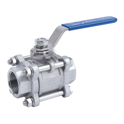
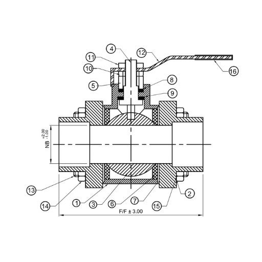
Ball Valves Three Piece, Full Bore (Screw End, Socket Weld) (150#, 300#, 600#, 800#)
Technical Data :
| Design Std. | As per ISO 17292 & BS 5351 |
| End Connection | Screwed End/Socket Weld |
| Testing & Std. | As per API 598 / ISO 5208 |
| Size, 150# | 15 mm to 50 mm (1/2" to 2") |
Material (MOC)
| Sr. No. | Description | Material |
| 1 | Body | WCB / CF8 / CF8M |
| 2 | Adaptor | WCB / CF8 / CF8M |
| 3 | Ball | CF8 / CF8M |
| 4 | Steam | SS304 / SS316 |
| 5 | Gland | SS304 / SS316 |
| 6 | Seat Ring | PTFE / GFT /CFT |
| 7 | Body Seal | PTFE / GFT /CFT |
| 8 | Gland Packing | PTFE / GFT /CFT |
| 9 | Steam Seal | PTFE / GFT /CFT |
| 10 | Gland Nut | MS/SS304 |
| 11 | Lever Nut | MS/SS304 |
| 12 | Lever | MS/SS |
| 13 | Stud | MS/SS304 |
| 14 | Stud Nut | MS/SS304 |
| 15 | Stud Washer | MS/SS304 |
| 16 | Lever Sleeve | PVC |
Dimensions 150#
| Size | NB | F/F | Thread Type |
| 15 | 12.5 | 62.5 | BSP/NPT/SW |
| 20 | 19.0 | 74.0 | BSP/NPT/SW |
| 25 | 25.0 | 87.0 | BSP/NPT/SW |
| 40 | 38.0 | 109.0 | BSP/NPT/SW |
| 50 | 50.0 | 110.0 | BSP/NPT/SW |
All Dimensions are in mm
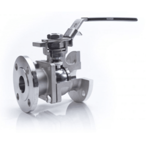
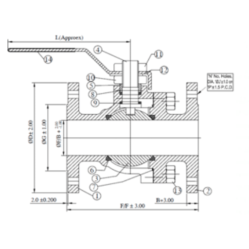
Ball Valves Two Piece, Metal Seated (150#, 300#)
Description
Kansei product KMS (Two-piece metal seated ball valve) in metal seated design as an additional option to our soft seated full port flanged series. This option increases the temperature rating to 750°F (399°C) and enhances wear resistance, while maintaining the proven safety and reliability of existing valves.Technical Data :
- Size Range: DN 15 (1/2”) – DN 200 (8”)
- Pressure: ASME Class 150 & 300
- Temperature range: Up to 400 deg. C
- Seat : SS 304 / SS316
- End Connections : Flanged ASME B16.5
- With ISO PAD
| Design Std. | As per ISO 17292 & BS 5351 |
| End Connection | Flanged End |
| Testing Std. | As per API 598 or ISO 5208 |
| Size 150# & 300# | 15 mm to 300 mm (1/2" to 12") |
MATERIALS (MOC)
| Sr. No. | Description | Material |
| 1 | Body | CI /WCB / CF8 / CF8M |
| 2 | Cap | CI / WCB / CF8 / CF8M |
| 3 | Ball | CF8 / CF8M |
| 4 | Stem | SS304 / SS316 |
| 5 | Gland | SS304 / SS316 |
| 6 | Seat Ring | SS304 / SS316 |
| 7 | Body Seal | PTFE / GFT / CFT |
| 8 | Gland Packing | PTFE / GFT / CFT |
| 9 | Stem Seal | PTFE / GFT / CFT |
| 10 | Gland Nut | MS / SS304 |
| 11 | Lever Nut | MS / SS304 |
| 12 | Lever | MS / SS |
| 13 | Stud & Nut | Ms / SS304 |
| 14 | Lever Sleeve | PVC |
| 15 | End Cap | PVC |
DIMENSIONS 150#
| Size | Dia D | PCD | F/F |
| 15 | 90 | 60.5 | 108 |
| 20 | 100 | 70 | 117 |
| 25 | 110 | 79.5 | 127 |
| 40 | 125 | 98.5 | 165 |
| 50 | 150 | 120.5 | 178 |
| 65 | 180 | 139.5 | 191 |
| 80 | 190 | 152.5 | 203 |
| 100 | 230 | 190.5 | 229 |
| 150 | 280 | 241.5 | 267 |
| 200 | 345 | 298.5 | 292 |
| 250 | 405 | 362 | 330 |
| 300 | 485 | 432 | 356 |
DIMENSIONS 300#
| Size | Dia D | PCD | F/F |
| 15 | 95 | 66.5 | 140 |
| 20 | 115 | 82.5 | 152 |
| 25 | 125 | 89 | 165 |
| 40 | 155 | 114.5 | 190 |
| 50 | 165 | 127 | 216 |
| 65 | 190 | 149 | 241 |
| 80 | 210 | 168.5 | 283 |
| 100 | 255 | 200 | 305 |
| 150 | 320 | 270 | 403 |
| 200 | 380 | 330 | 419 |
| 250 | 445 | 387.5 | 457 |
| 300 | 520 | 451 | 502 |
All dimensions are in mm.
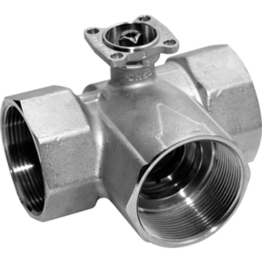
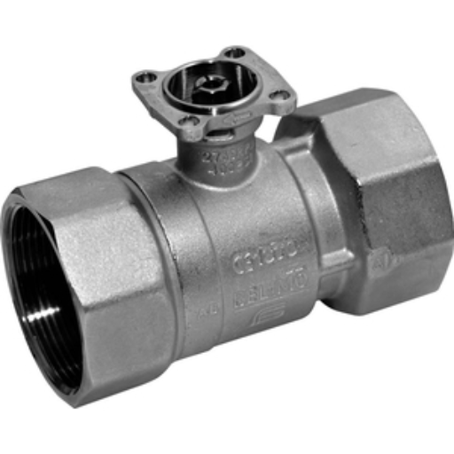
Belimo Ball Valves
Applications
The ball valve offers high close-off or change-over capabilities without leakage - that's efficiency.Achieve Control and Reliability
High Performance for Aggressive Applications
Specification
Pattern: 2-way, 3-way kvs range (kvs): 1.1...3.0 kvs, 3.1...6.5 kvs, 6.6...14 kvs, 15...40 kvs, 41...170 kvs, 171...1000 kvs Valve size (mm): 15 mm, 20 mm, 25 mm, 32 mm, 40 mm, 50 mm, 65 mm, 80 mm, 100 mm, 125 mm, 150 mm Pipe connection: Flange, Internal thread
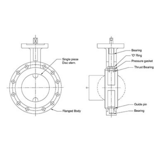
BUTTERFLY VALVE PFA/PTFE Lined, Centric Bi-directional
Applications :
This type of valves are used for multitude and corrosive application, Hazardous and pure liquid, gas, & vapors, free flowing. e.g.: Pharma, foundries and mining, chemicals and petrochemicals, pulp and paper industries, under vessels, & specially used where constant torque and no maintenance is required . Suitable for on-off and control servicesTECHNICAL DATA
Type: Wafer type, Lug type, Flange typeWafer type & Lug type Size: 2” (50 mm) to 12” (300 mm)
Flange type Size: 14” (350 mm) to 16” (400 mm) Design: Centric Bi-directional Pressure: PN10, PN16 Seat: PTFE, PFA, PFA CONDUCTIVE, TFM, TFM CONDUCTIVE Flange Suit To: ANSI 150#Design, Manufacturing and Testing Standards – Technology at a Glance
Kansei PFA/PTFE Lined Centric Bi-directional Butterfly valves are designed to ensure a tight fit around the disc for bubble tight shut off in both direction and provide a constant torque with no maintenance. “A major advantage of Kansei product is an International compatibility.”
The Exceptional Design of one-piece thin disc stem lined with 3mm molded PFA providing high Kv value. The liner and disc are the only two valve parts in contact with the medium. Kansei improved design of disc leading to less deflection at higher pressure and tighter in line seal and for stem sealing system. Primary shaft sealing by preloaded contact between disc and liner hub and the secondary shaft seal by oversizing the shaft diameter in relation to the shaft hole in the liner. The liner and disc are molded and machined to close tolerances to provide low torque, less stress and deformation using opening and closing. PTFE atmospheric seat protects internal components from atmospheric corrosion and provides locating ring for actuator mounting. Fully encapsulated bottom shaft eliminates potential leak path at bottom of valve and eliminates the necessity for further sealing elements- Design standard as per EN 593 or API 609 as standard, another applicable standard on request.
- Testing standard as per API 598 or BS EN 12266-I as standard. 100% bubble tight shut off valve.
- Certificate EN10204 Type 3.1 as standard & Manufacturing under Quality system ISO 9001: 2015.
- Casting inspection as per MSS-SP-55 as standard. Another applicable standard on request.
- Trims available with combination of various Casting material like CI/ DI/ WCB/ CF8M/ CF3M/ GR. 4A-5A/ etc. and Seat Material PTFE.
- 100% factory tested (Hydro, Pneumatic) and Inspected valves as per standard.
- Lever / Gear / Pneumatic / Electric Operation as per customer requirement.
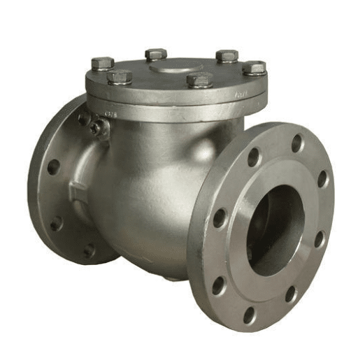
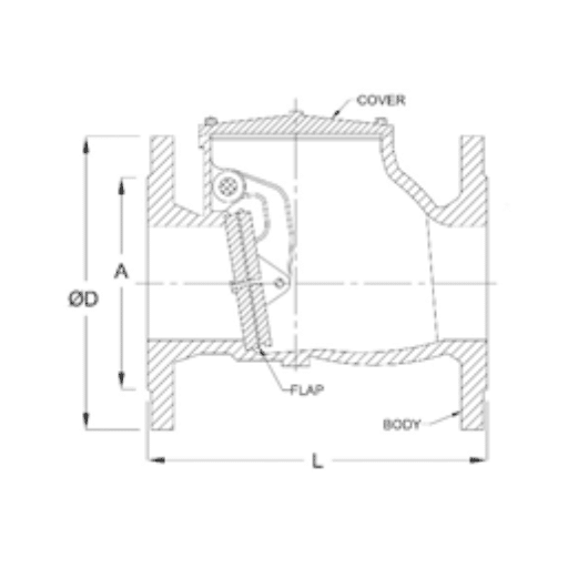
CHECK VALVE / NON RETURN VALVE ( NRV ), Flange End (PN10, PN16)
TECHNICAL DATA
| Design Std. | As per API 602 / ASME B16.34 |
| Testing Std. | As per API 598 |
| End Connection | Flanged End |
| Size | 30 mm to 300 mm, PN10 / PN16 |
Dimensions PN10
| Size | Dia D | L | A |
| 30 | 140 | 180 | 30 |
| 40 | 150 | 180 | 40 |
| 50 | 165 | 200 | 50 |
| 65 | 185 | 240 | 65 |
| 80 | 200 | 260 | 80 |
| 100 | 220 | 300 | 100 |
| 125 | 250 | 350 | 125 |
| 150 | 285 | 400 | 150 |
| 200 | 340 | 500 | 200 |
| 250 | 395 | 600 | 250 |
| 300 | 445 | 700 | 300 |
Dimensions PN16
| Size | Dia D | L | A |
| 30 | 140 | 180 | 30 |
| 40 | 150 | 180 | 40 |
| 50 | 165 | 200 | 50 |
| 65 | 185 | 240 | 65 |
| 80 | 200 | 260 | 80 |
| 100 | 220 | 300 | 100 |
| 125 | 250 | 350 | 125 |
| 150 | 285 | 400 | 150 |
| 200 | 340 | 500 | 200 |
| 250 | 405 | 600 | 250 |
| 300 | 460 | 700 | 300 |
All dimensions are in mm.
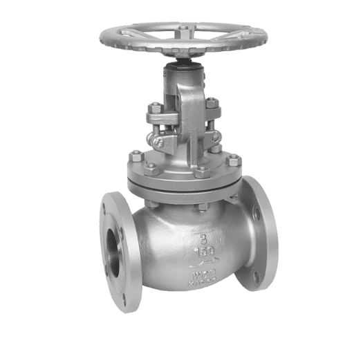
Globe Valve – Flanged End (150#, 300#)
TECHNICAL DATA
| Design Std. | As per BS 1873 / ASME B 16.34 |
| End Connection | Flanged End |
| Testing & Std. | As per API 598 or ISO 5208 |
| Size, 150# | 25 mm to 300 mm (1” to 12”) |
| Size, 300# | 50 mm to 300 mm (2” to 12”) |
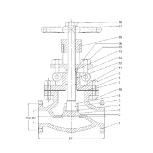
Bill Of Material
| Sr. No. | Description | Material |
| 1 | Body | WCB / CF8 / CF8M |
| 2 | Body seat | SS410 (13% CR)/CF8/CF8M |
| 3 | Disc | WCB +13% CR STEEL |
| 4 | Disc washer | 13% CR STEEL |
| 5 | Stem | SS410 / SS304 / SS316 |
| 6 | Disc Stem Nut | 13% CR STEEL |
| 7 | Gasket | SPW SS304 GRAPHITE FILL |
| 8 | Bonnet | WCB/CF8/CF8M |
| 9 | Stud | ASTM A193 Gr. B7 |
| 10 | Stud Nut | ASTM A194 Gr. B2H |
| 11 | Back Seat Bush | SS410/SS304/SS316 |
| 12 | Spacer | 13% CR STEEL |
| 13 | Packing | GRAPHITE |
| 14 | Eye Bolt | MS/SS |
| 15 | Eye Bolt Nut | MS/SS |
| 16 | Gland | SS410/SS304/SS316 |
| 17 | Hand Wheel | MALLEABLE IRON |
| 18 | Hand Wheel Nut | MS |
| 19 | Yoke Sleeve | EN8 |
Dimensions 150#
| Size | Dia D | PCD | F/F |
| 25 | 110 | 79.5 | 127 |
| 40 | 125 | 98.5 | 165 |
| 50 | 150 | 120.5 | 203 |
| 65 | 180 | 139.5 | 216 |
| 80 | 190 | 152.5 | 241 |
| 100 | 230 | 190.5 | 292 |
| 150 | 280 | 241.5 | 406 |
| 200 | 345 | 298.5 | 495 |
| 250 | 405 | 362 | 622 |
| 300 | 485 | 432 | 698 |
Dimensions 300#
| Size | Dia D | PCD | F/F |
| 50 | 165 | 127 | 267 |
| 65 | 190 | 149 | 292 |
| 80 | 210 | 168.5 | 318 |
| 100 | 255 | 200 | 356 |
| 150 | 320 | 270 | 444 |
| 200 | 380 | 330 | 559 |
| 250 | 445 | 387.5 | 622 |
| 300 | 520 | 451 | 711 |


POT-BASKET TYPE STRAINER (ANSI 150#, 300#)
Applications:
Strainer can be used in liquid as well as gas line, Regulator and valve protection, steam traps protections, flow meter and pump protections, heat exchanger and refrigeration set protection, Suitable for Hazardous environments. Y-Strainers and pot basket type strainers is a device for mechanically removing unwanted solids from liquid, gas or steam lines by means of a perforated or wire mesh straining element. Where the amount of material to be removed from the flow is relatively small, resulting in long intervals between screen cleanings, the strainer screen is manually cleaned by shutting down the line and removing the strainer cap.Technical Data :
| Design Std. | As per ASME B16.34 |
| Testing Std. | As per API 598 |
| End Connection | Flanged Drill as per ANSI B16.5 |
| Material | Body : IS 2062, Seal : NBR / PTFE / Graphite + SS, Mesh : SS |
| Shell Wall Thickness | As per ANSI B16.34 |
| Size | 2" to 18", Class 150, 300 |
Dimensions 150#
| Size | F/F | A | B |
| 50 | 320 | 190 | 285 |
| 80 | 360 | 200 | 320 |
| 100 | 400 | 210 | 360 |
| 125 | 460 | 230 | 430 |
| 150 | 510 | 240 | 430 |
| 200 | 560 | 280 | 530 |
| 250 | 810 | 420 | 635 |
| 300 | 890 | 430 | 715 |
Dimensions 300#
| Size | F/F | A | B |
| 50 | 380 | 200 | 305 |
| 80 | 420 | 235 | 400 |
| 100 | 475 | 260 | 405 |
| 125 | 510 | 275 | 435 |
| 150 | 620 | 295 | 490 |
| 200 | 630 | 345 | 560 |
| 250 | 900 | 390 | 690 |
| 300 | 1000 | 440 | 770 |
All dimensions are in mm.
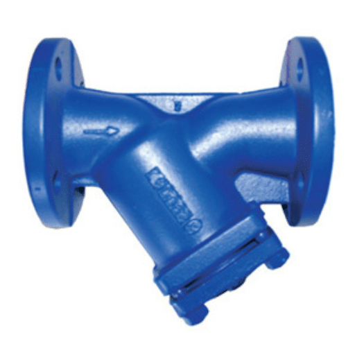
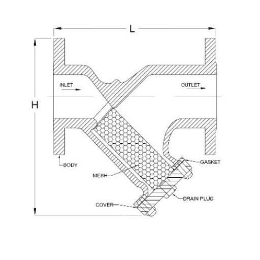
Y-Type Strainers (ANSI 150#, 300#)
Applications:
Strainer can be used in liquid as well as gas line, Regulator and valve protection, steam traps protections, flow meter and pump protections, heat exchanger and refrigeration set protection, Suitable for Hazardous environments. Y-Strainers and pot basket type strainers is a device for mechanically removing unwanted solids from liquid, gas or steam lines by means of a perforated or wire mesh straining element. Where the amount of material to be removed from the flow is relatively small, resulting in long intervals between screen cleanings, the strainer screen is manually cleaned by shutting down the line and removing the strainer capTechnical Data :
| Design Std. | As per ASME B16.34 |
| Testing Std. | As per API 598 |
| End Connection | Flanged End as per ANSI B16.5, F to F as per ANSI B16.10 |
| Shell Wall Thickness | As per ANSI B16.34 |
| Size 150# & 300# | 50 mm to 300 mm (2” to 12”) |
| Standard Trims | WCB / CF8M, Mesh : SS |
Dimensions 150#
| Size | ~L | ~H |
| 50 | 225 | 190 |
| 80 | 315 | 270 |
| 100 | 370 | 305 |
| 150 | 470 | 400 |
| 200 | 600 | 490 |
| 250 | 695 | 670 |
| 300 | 810 | 800 |
Dimensions 300#
| Size | ~L | ~H |
| 50 | 270 | 190 |
| 80 | 320 | 270 |
| 100 | 355 | 305 |
| 150 | 450 | 400 |
| 200 | 560 | 490 |
| 250 | 730 | 670 |
| 300 | 850 | 800 |
All dimensions are in mm.
