

")
")


POT-BASKET TYPE STRAINER (ANSI 150#, 300#)
Applications:
Strainer can be used in liquid as well as gas line, Regulator and valve protection, steam traps protections, flow meter and pump protections, heat exchanger and refrigeration set protection, Suitable for Hazardous environments.
Y-Strainers and pot basket type strainers is a device for mechanically removing unwanted solids from liquid, gas or steam lines by means of a perforated or wire mesh straining element. Where the amount of material to be removed from the flow is relatively small, resulting in long intervals between screen cleanings, the strainer screen is manually cleaned by shutting down the line and removing the strainer cap.
Technical Data :
| Design Std. | As per ASME B16.34 |
| Testing Std. | As per API 598 |
| End Connection | Flanged Drill as per ANSI B16.5 |
| Material | Body : IS 2062, Seal : NBR / PTFE / Graphite + SS, Mesh : SS |
| Shell Wall Thickness | As per ANSI B16.34 |
| Size | 2″ to 18″, Class 150, 300 |
Dimensions 150#
| Size | F/F | A | B |
| 50 | 320 | 190 | 285 |
| 80 | 360 | 200 | 320 |
| 100 | 400 | 210 | 360 |
| 125 | 460 | 230 | 430 |
| 150 | 510 | 240 | 430 |
| 200 | 560 | 280 | 530 |
| 250 | 810 | 420 | 635 |
| 300 | 890 | 430 | 715 |
Dimensions 300#
| Size | F/F | A | B |
| 50 | 380 | 200 | 305 |
| 80 | 420 | 235 | 400 |
| 100 | 475 | 260 | 405 |
| 125 | 510 | 275 | 435 |
| 150 | 620 | 295 | 490 |
| 200 | 630 | 345 | 560 |
| 250 | 900 | 390 | 690 |
| 300 | 1000 | 440 | 770 |
All dimensions are in mm.
General Notes :
- Customization and automation as per customer requirements.
- Certificate of compliance to EN10204 Type 3.1 as standard.
- Safety stock as per customer requirements.
- 100% factory tested and inspected valves as per standard.
- Other trims also available as per customer requirements.
- Support to customers for other product requirements from sources.
- Consult to Factory for Other Details.
Related products
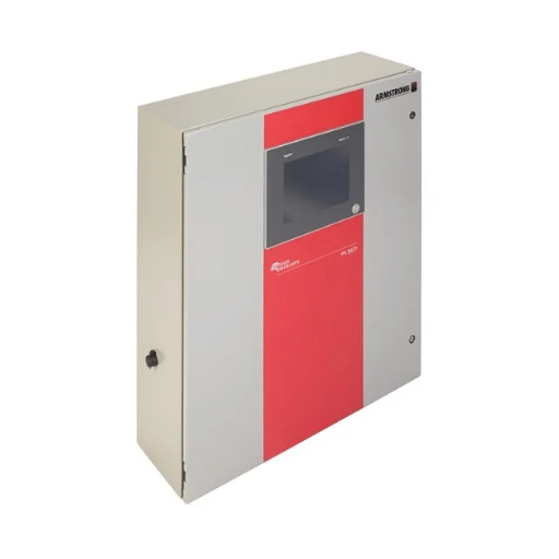
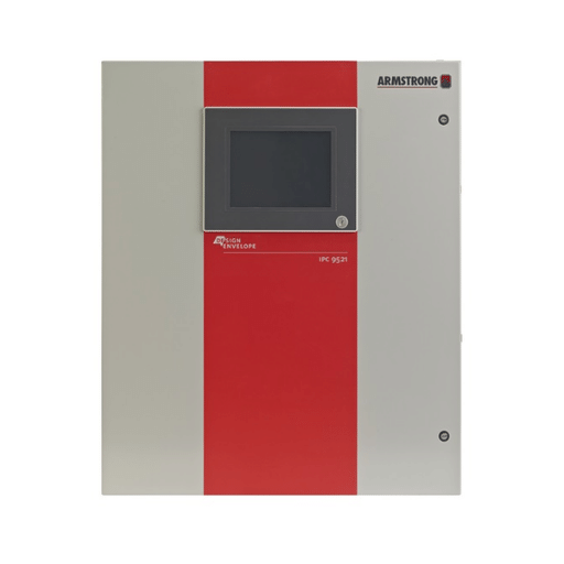
Armstrong Design Envelope 9521 Integrated Plant Control System (IPC 9521)
- Applications-Automated chiller plant control for optimizing variable primary flow water-cooled chiller plants. The 9521 IPC works in a variable primary configuration and keeps the entire plant including water-cooled chillers, cooling towers, chilled water and condenser pumps running smoothly.
- Description-The Armstrong Integrated Water-Cooled Chiller Plant Control System (IPC) boosts energy efficiencies of new and existing chiller plant installations to leading class levels. The IPC 9521 works with all variable primary configurations, keeping the entire plant – including water-cooled chillers, cooling towers, chilled water and condenser pumps – running at optimum performance and occupant comfort.
- Configuration-Integrates with all brands of chillers, pumps, and automation systems. Installs directly with chiller plant equipment. If preferred, the IPC connects seamlessly with any central building automation system (BAS) maintaining full control of the chilled water plant through the BAS
- Performance range-Controls up to five chillers, five cooling towers and five pumps. No limitations in plant size and cooling capacity.
- Power Range-No limitations in plant cooling capacity
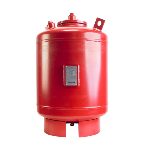
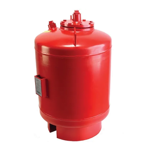
Armstrong Expansion Tanks
- Applications-Pressure stabilization in water based mechanical systems such as booster installations, boiler systems, and chiller plants
- Description-Armstrong Expansion Tanks are designed to reduce tank sizes by up to 80% over standard designs. Expansion tanks use compressed air to maintain system pressures by accepting and expelling the changing volume of water as it heats and cools. Diaphragm or bladder tank designs isolate the expanded water from the pressure controlling air cushion – which is pre-charged at the factory and can be adjusted in the field to meet final system requirements
- Materials (MOC)-Carbon steel (shell), heavy duty Butyl (diaphragm)
- Performance range-AET plain steel expansion tanks: 15 to 525 USgpm flow. AX diaphragm expansion tanks: 8 to 211 USgpm flow. Type L bladder type expansion tanks: 10 to 1056 USgpm flow.
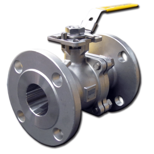
Ball Valves Two Piece, Full Bore, Flange end (150#, 300#)
Technical Data :
| Design Std. | As per ISO 17292 & BS 5351 |
| End Connection | Flanged End |
| Testing Std. | As per API 598 or ISO 5208 |
| Size 150# & 300# | 15 mm to 300 mm (1/2" to 12") |
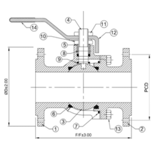
BILL OF MATERIALS
| Sr. No. | Description | Material |
| 1 | Body | CI / WCB / CF8 / CF8M |
| 2 | Adaptor | CI / WCB / CF8 / CF8M |
| 3 | Ball | CF8 / CF8M |
| 4 | Stem | SS304 / SS316 |
| 5 | Gland | SS304 / SS316 |
| 6 | Seat Ring | PTFE / GFT / CFT |
| 7 | Body Seal | PTFE / GFT / CFT |
| 8 | Gland Packing | PTFE / GFT / CFT |
| 9 | Stem Seal | PTFE / GFT / CFT |
| 10 | Gland Nut | MS / SS304 |
| 11 | Lever Nut | MS / SS304 |
| 12 | Lever | MS / SS |
| 13 | Stud | MS / SS304 |
| 14 | Stud Nut | MS/SS304 |
| 15 | Stud Washer | MS/SS304 |
| 16 | Lever Sleeve | PVC |
DIMENSIONS 150#
| Size | Dia D | PCD | F/F |
| 15 | 90 | 60.5 | 108 |
| 20 | 100 | 70 | 117 |
| 25 | 110 | 79.5 | 127 |
| 40 | 125 | 98.5 | 165 |
| 50 | 150 | 120.5 | 178 |
| 65 | 180 | 139.5 | 191 |
| 80 | 190 | 152.5 | 203 |
| 100 | 230 | 190.5 | 229 |
| 150 | 280 | 241.5 | 267 |
| 200 | 345 | 298.5 | 292 |
| 250 | 405 | 362 | 330 |
| 300 | 485 | 432 | 356 |
DIMENSIONS 300#
| Size | Dia D | PCD | F/F |
| 15 | 95 | 66.5 | 140 |
| 20 | 115 | 82.5 | 152 |
| 25 | 125 | 89 | 165 |
| 40 | 155 | 114.5 | 190 |
| 50 | 165 | 127 | 216 |
| 65 | 190 | 149 | 241 |
| 80 | 210 | 168.5 | 283 |
| 100 | 255 | 200 | 305 |
| 150 | 320 | 270 | 403 |
| 200 | 380 | 330 | 419 |
| 250 | 445 | 387.5 | 457 |
| 300 | 520 | 451 | 502 |
All dimensions are in mm.


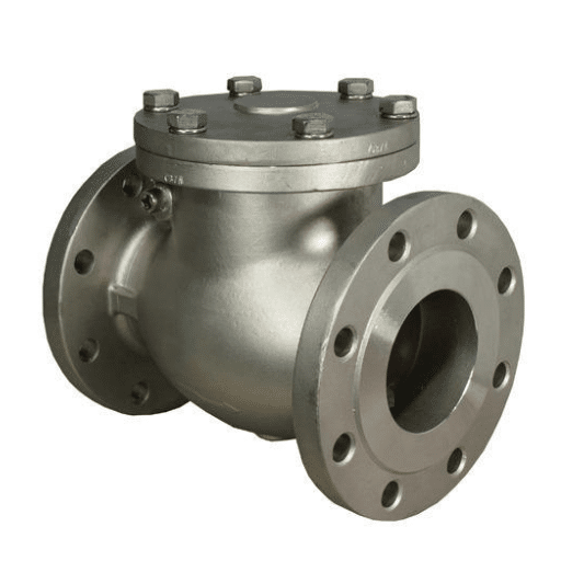
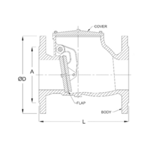
CHECK VALVE / NON RETURN VALVE ( NRV ), Flange End (PN10, PN16)
TECHNICAL DATA
| Design Std. | As per API 602 / ASME B16.34 |
| Testing Std. | As per API 598 |
| End Connection | Flanged End |
| Size | 30 mm to 300 mm, PN10 / PN16 |
Dimensions PN10
| Size | Dia D | L | A |
| 30 | 140 | 180 | 30 |
| 40 | 150 | 180 | 40 |
| 50 | 165 | 200 | 50 |
| 65 | 185 | 240 | 65 |
| 80 | 200 | 260 | 80 |
| 100 | 220 | 300 | 100 |
| 125 | 250 | 350 | 125 |
| 150 | 285 | 400 | 150 |
| 200 | 340 | 500 | 200 |
| 250 | 395 | 600 | 250 |
| 300 | 445 | 700 | 300 |
Dimensions PN16
| Size | Dia D | L | A |
| 30 | 140 | 180 | 30 |
| 40 | 150 | 180 | 40 |
| 50 | 165 | 200 | 50 |
| 65 | 185 | 240 | 65 |
| 80 | 200 | 260 | 80 |
| 100 | 220 | 300 | 100 |
| 125 | 250 | 350 | 125 |
| 150 | 285 | 400 | 150 |
| 200 | 340 | 500 | 200 |
| 250 | 405 | 600 | 250 |
| 300 | 460 | 700 | 300 |
All dimensions are in mm.
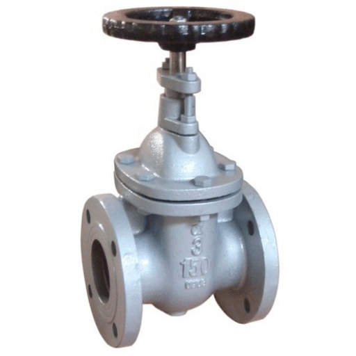
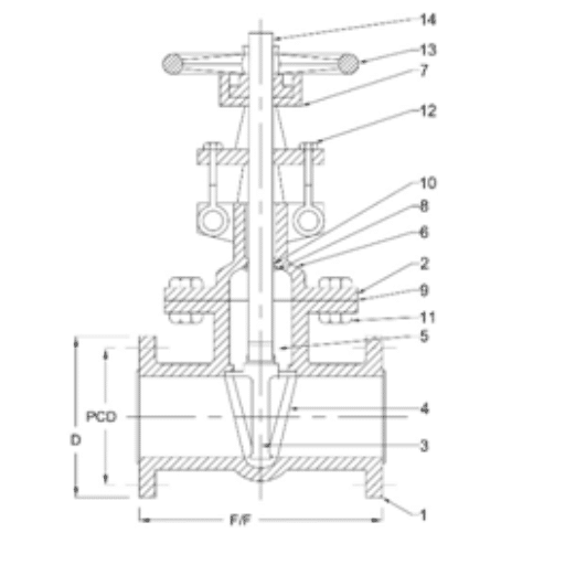
GATE VALVE, Flanged End (150# , 300#)
Technical Data
| Design Std. | As per BS 1414 |
| End Connection | Flanged End |
| Testing & Std. | As per API 598 / ISO 5208 |
| Size, 150# & 300# | 15 mm to 300 mm (1/2" to 12") |
Bill Of Material
| Sr. No. | Description | Material |
| 1 | Body | WCB / CF8 / CF8M |
| 2 | Bonnet | WCB / CF8 / CF8M |
| 3 | Wedge | WCB (13% CR) / CF8 / CF8M |
| 4 | Seat Ring | SS410 (13% CR) / CF8 / CF8M |
| 5 | Stem | SS410 / SS304 / SS316 |
| 6 | Gland | SS410 / SS304 / SS316 |
| 7 | Yoke Sleeve | SS410 / SS304 / SS316 |
| 8 | Back Seat Bush | CS/CF8/CF8M |
| 9 | Gasket | EN8 |
| 10 | Gland Packing | MS/SS |
| 11 | Bonet Stud | MALLEABLE IRON |
| 12 | Bolt | MS |
| 13 | Hand wheel | SPW SS304 GRAPHITE FILLED |
| 14 | Hand wheel Nut | GRAPHITE |
Dimensions 150#
| Size | Dia D | PCD | F/F |
| 15 | 90 | 60.5 | 108 |
| 20 | 100 | 70 | 117 |
| 25 | 110 | 79.5 | 127 |
| 40 | 125 | 98.5 | 165 |
| 50 | 150 | 120.5 | 178 |
| 65 | 180 | 139.5 | 191 |
| 80 | 190 | 152.5 | 203 |
| 100 | 230 | 190.5 | 229 |
| 150 | 280 | 241.5 | 267 |
| 200 | 345 | 298.5 | 292 |
| 250 | 405 | 362 | 330 |
| 300 | 485 | 432 | 356 |
Dimensions 300#
| Size | Dia D | PCD | F/F |
| 15 | 95 | 66.5 | 140 |
| 20 | 115 | 82.5 | 152 |
| 25 | 125 | 89 | 165 |
| 40 | 155 | 114.5 | 190 |
| 50 | 165 | 127 | 216 |
| 65 | 190 | 149 | 241 |
| 80 | 210 | 168.5 | 283 |
| 100 | 255 | 200 | 305 |
| 150 | 320 | 270 | 403 |
| 200 | 380 | 330 | 419 |
| 250 | 445 | 387.5 | 457 |
| 300 | 520 | 451 | 502 |
All dimensions are in mm.
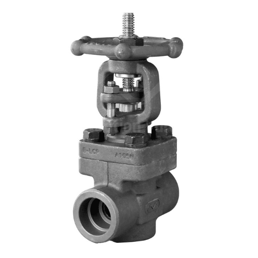
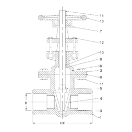
GATE VALVE, Socket weld (800#)
Technical Data
| Design Std. | As per BS 1414 |
| End Connection | Threaded End |
| Testing & Std. | As per API 598 / ISO 5208 |
| Size, 150# & 300# | 15 mm to 80 mm (1/2" to 3") |
Bill Of Material
| Sr. No. | Description | Material |
| 1 | Body | WCB / CF8 / CF8M |
| 2 | Bonnet | WCB / CF8 / CF8M |
| 3 | Wedge | WCB (13% CR) / CF8 / CF8M |
| 4 | Seat Ring | SS410 (13% CR) / CF8 / CF8M |
| 5 | Stem | SS410 / SS304 / SS316 |
| 6 | Gland | SS410 / SS304 / SS316 |
| 7 | Yoke Sleeve | SS410 / SS304 / SS316 |
| 8 | Back Seat Bush | CS/CF8/CF8M |
| 9 | Gasket | EN8 |
| 10 | Gland Packing | MS/SS |
| 11 | Bonet Stud | MALLEABLE IRON |
| 12 | Bolt | MS |
| 13 | Hand wheel | SPW SS304 GRAPHITE FILLED |
| 14 | Hand wheel Nut | GRAPHITE |
Dimensions 800#
| Size | F/F | B |
| 15 | 51 | 62 |
| 20 | 55 | 66 |
| 25 | 63 | 78 |
| 30 | 71 | 85 |
| 40 | 73 | 94 |
| 50 | 83 | 101 |
| 60 | 108 | 127 |
| 80 | 117 | 143 |
All dimensions are in mm.
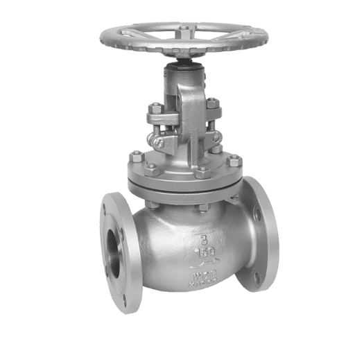
Globe Valve – Flanged End (150#, 300#)
TECHNICAL DATA
| Design Std. | As per BS 1873 / ASME B 16.34 |
| End Connection | Flanged End |
| Testing & Std. | As per API 598 or ISO 5208 |
| Size, 150# | 25 mm to 300 mm (1” to 12”) |
| Size, 300# | 50 mm to 300 mm (2” to 12”) |
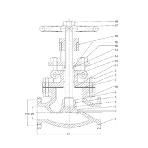
Bill Of Material
| Sr. No. | Description | Material |
| 1 | Body | WCB / CF8 / CF8M |
| 2 | Body seat | SS410 (13% CR)/CF8/CF8M |
| 3 | Disc | WCB +13% CR STEEL |
| 4 | Disc washer | 13% CR STEEL |
| 5 | Stem | SS410 / SS304 / SS316 |
| 6 | Disc Stem Nut | 13% CR STEEL |
| 7 | Gasket | SPW SS304 GRAPHITE FILL |
| 8 | Bonnet | WCB/CF8/CF8M |
| 9 | Stud | ASTM A193 Gr. B7 |
| 10 | Stud Nut | ASTM A194 Gr. B2H |
| 11 | Back Seat Bush | SS410/SS304/SS316 |
| 12 | Spacer | 13% CR STEEL |
| 13 | Packing | GRAPHITE |
| 14 | Eye Bolt | MS/SS |
| 15 | Eye Bolt Nut | MS/SS |
| 16 | Gland | SS410/SS304/SS316 |
| 17 | Hand Wheel | MALLEABLE IRON |
| 18 | Hand Wheel Nut | MS |
| 19 | Yoke Sleeve | EN8 |
Dimensions 150#
| Size | Dia D | PCD | F/F |
| 25 | 110 | 79.5 | 127 |
| 40 | 125 | 98.5 | 165 |
| 50 | 150 | 120.5 | 203 |
| 65 | 180 | 139.5 | 216 |
| 80 | 190 | 152.5 | 241 |
| 100 | 230 | 190.5 | 292 |
| 150 | 280 | 241.5 | 406 |
| 200 | 345 | 298.5 | 495 |
| 250 | 405 | 362 | 622 |
| 300 | 485 | 432 | 698 |
Dimensions 300#
| Size | Dia D | PCD | F/F |
| 50 | 165 | 127 | 267 |
| 65 | 190 | 149 | 292 |
| 80 | 210 | 168.5 | 318 |
| 100 | 255 | 200 | 356 |
| 150 | 320 | 270 | 444 |
| 200 | 380 | 330 | 559 |
| 250 | 445 | 387.5 | 622 |
| 300 | 520 | 451 | 711 |
