

")
")
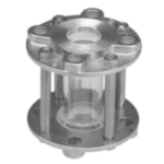
Full View Sight Glass (PN10)
Applications:
Industrial facilities, oil refineries, bath soap manufacturing plane, gas industries, petrochemical complex, high viscous process media, building construction, environmental water treatments, synthetics, plastic and resin industries, polymer manufacturing plant, food industries (chocolate, sauce etc.), fertilizer industries etc.
Technical Data :
| Design Std. | As per BS 5352 |
| Testing Std. | As per API 598 |
| End Connection | As per ANSI B16.5 |
| Size | ½” to 4” (15 mm to100 mm) |
| Pressure rating | PN10 |
| Maximum working pressure | 10 Kg/cm2 |
| Test pressure | 15 Kg/cm2 |
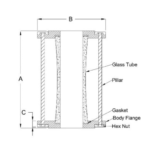
Dimensions
| Size | A | B | C |
| 15 | 153 | 51 | 137 |
| 20 | 153 | 51 | 137 |
| 25 | 153 | 51 | 137 |
| 40 | 178 | 64 | 146 |
| 50 | 190 | 76 | 190 |
| 75 | 229 | 102 | 132 |
| 100 | 299 | 127 | 283 |
All dimensions are in mm.
General Notes :
- Customization and Automation as per customer requirements.
- Certificate of compliance to EN10204 Type 3.1 as standard.
- Safety stock as per customer requirements.
- 100% factory tested and inspected valves as per standard.
- Other trims also available as per customer requirements.
- Support to customers for other product requirements from sources.
- Consult to Factory for Torque and Other Details.
Related products
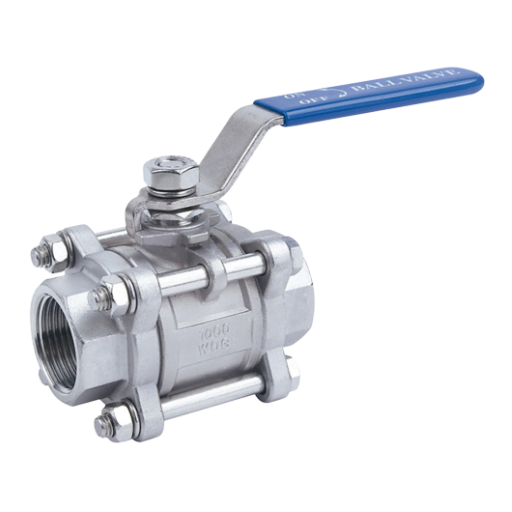
Ball Valves Three Piece, Full Bore (Screw End, Socket Weld) (150#, 300#, 600#, 800#)
Technical Data :
| Design Std. | As per ISO 17292 & BS 5351 |
| End Connection | Screwed End/Socket Weld |
| Testing & Std. | As per API 598 / ISO 5208 |
| Size, 150# | 15 mm to 50 mm (1/2" to 2") |
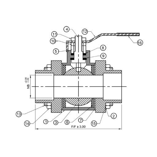
Material (MOC)
| Sr. No. | Description | Material |
| 1 | Body | WCB / CF8 / CF8M |
| 2 | Adaptor | WCB / CF8 / CF8M |
| 3 | Ball | CF8 / CF8M |
| 4 | Steam | SS304 / SS316 |
| 5 | Gland | SS304 / SS316 |
| 6 | Seat Ring | PTFE / GFT /CFT |
| 7 | Body Seal | PTFE / GFT /CFT |
| 8 | Gland Packing | PTFE / GFT /CFT |
| 9 | Steam Seal | PTFE / GFT /CFT |
| 10 | Gland Nut | MS/SS304 |
| 11 | Lever Nut | MS/SS304 |
| 12 | Lever | MS/SS |
| 13 | Stud | MS/SS304 |
| 14 | Stud Nut | MS/SS304 |
| 15 | Stud Washer | MS/SS304 |
| 16 | Lever Sleeve | PVC |
Dimensions 150#
| Size | NB | F/F | Thread Type |
| 15 | 12.5 | 62.5 | BSP/NPT/SW |
| 20 | 19.0 | 74.0 | BSP/NPT/SW |
| 25 | 25.0 | 87.0 | BSP/NPT/SW |
| 40 | 38.0 | 109.0 | BSP/NPT/SW |
| 50 | 50.0 | 110.0 | BSP/NPT/SW |
All Dimensions are in mm


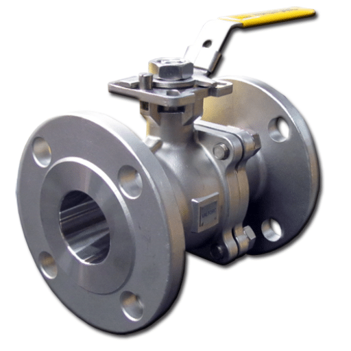
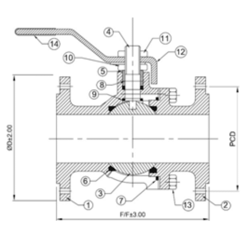
Ball Valves Three Piece, Full Bore, Flange end (150#, 300#)
Technical Data :
| Design Std. | As per ISO 17292 & BS 5351 |
| End Connection | Flanged End |
| Testing Std. | As per API 598 or ISO 5208 |
| Size 150# & 300# | 15 mm to 300 mm (1/2" to 12") |
MATERIALS (MOC)
| Sr. No. | Description | Material |
| 1 | Body | CI /WCB / CF8 / CF8M |
| 2 | Adaptor | CI / WCB / CF8 / CF8M |
| 3 | Ball | CF8 / CF8M |
| 4 | Stem | SS304 / SS316 |
| 5 | Gland | SS304 / SS316 |
| 6 | Seat Ring | PTFE / GFT / CFT |
| 7 | Body Seal | PTFE / GFT / CFT |
| 8 | Gland Packing | PTFE / GFT / CFT |
| 9 | Stem Seal | PTFE / GFT / CFT |
| 10 | Gland Nut | MS / SS304 |
| 11 | Lever Nut | MS / SS304 |
| 12 | Lever | MS / SS |
| 13 | Stud | Ms / SS304 |
| 14 | Stud Nut | Ms / SS304 |
| 15 | Stud Washer | Ms / SS304 |
| 16 | Lever Washer | PVC |
DIMENSIONS 150#
| Size | Dia D | PCD | F/F |
| 15 | 90 | 60.5 | 108 |
| 20 | 100 | 70 | 117 |
| 25 | 110 | 79.5 | 127 |
| 40 | 125 | 98.5 | 165 |
| 50 | 150 | 120.5 | 178 |
| 65 | 180 | 139.5 | 191 |
| 80 | 190 | 152.5 | 203 |
| 100 | 230 | 190.5 | 229 |
| 150 | 280 | 241.5 | 267 |
| 200 | 345 | 298.5 | 292 |
| 250 | 405 | 362 | 330 |
| 300 | 485 | 432 | 356 |
DIMENSIONS 300#
| Size | Dia D | PCD | F/F |
| 15 | 95 | 66.5 | 140 |
| 20 | 115 | 82.5 | 152 |
| 25 | 125 | 89 | 165 |
| 40 | 155 | 114.5 | 190 |
| 50 | 165 | 127 | 216 |
| 65 | 190 | 149 | 241 |
| 80 | 210 | 168.5 | 283 |
| 100 | 255 | 200 | 305 |
| 150 | 320 | 270 | 403 |
| 200 | 380 | 330 | 419 |
| 250 | 445 | 387.5 | 457 |
| 300 | 520 | 451 | 502 |
All dimensions are in mm.
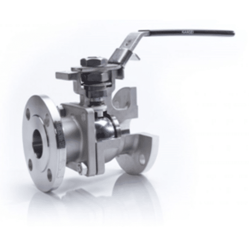
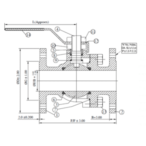
Ball Valves Two Piece, Full Bore, Flange end (150#, 300#)
Technical Data :
| Design Std. | As per ISO 17292 & BS 5351 |
| End Connection | Flanged End |
| Testing Std. | As per API 598 or ISO 5208 |
| Size 150# & 300# | 15 mm to 300 mm (1/2" to 12") |
BILL OF MATERIALS
| Sr. No. | Description | Material |
| 1 | Body | CI / WCB / CF8 / CF8M |
| 2 | Adaptor | CI / WCB / CF8 / CF8M |
| 3 | Ball | CF8 / CF8M |
| 4 | Stem | SS304 / SS316 |
| 5 | Gland | SS304 / SS316 |
| 6 | Seat Ring | PTFE / GFT / CFT |
| 7 | Body Seal | PTFE / GFT / CFT |
| 8 | Gland Packing | PTFE / GFT / CFT |
| 9 | Stem Seal | PTFE / GFT / CFT |
| 10 | Gland Nut | MS / SS304 |
| 11 | Lever Nut | MS / SS304 |
| 12 | Lever | MS / SS |
| 13 | Stud | MS / SS304 |
| 14 | Stud Nut | MS/SS304 |
| 15 | Stud Washer | MS/SS304 |
| 16 | Lever Sleeve | PVC |
DIMENSIONS 150#
| Size | Dia D | PCD | F/F |
| 15 | 90 | 60.5 | 108 |
| 20 | 100 | 70 | 117 |
| 25 | 110 | 79.5 | 127 |
| 40 | 125 | 98.5 | 165 |
| 50 | 150 | 120.5 | 178 |
| 65 | 180 | 139.5 | 191 |
| 80 | 190 | 152.5 | 203 |
| 100 | 230 | 190.5 | 229 |
| 150 | 280 | 241.5 | 267 |
| 200 | 345 | 298.5 | 292 |
| 250 | 405 | 362 | 330 |
| 300 | 485 | 432 | 356 |
DIMENSIONS 300#
| Size | Dia D | PCD | F/F |
| 15 | 95 | 66.5 | 140 |
| 20 | 115 | 82.5 | 152 |
| 25 | 125 | 89 | 165 |
| 40 | 155 | 114.5 | 190 |
| 50 | 165 | 127 | 216 |
| 65 | 190 | 149 | 241 |
| 80 | 210 | 168.5 | 283 |
| 100 | 255 | 200 | 305 |
| 150 | 320 | 270 | 403 |
| 200 | 380 | 330 | 419 |
| 250 | 445 | 387.5 | 457 |
| 300 | 520 | 451 | 502 |
All dimensions are in mm.
Ball Valves Two Piece, Metal Seated (150#, 300#)
Description
Kansei product KMS (Two-piece metal seated ball valve) in metal seated design as an additional option to our soft seated full port flanged series. This option increases the temperature rating to 750°F (399°C) and enhances wear resistance, while maintaining the proven safety and reliability of existing valves.Technical Data :
- Size Range: DN 15 (1/2”) – DN 200 (8”)
- Pressure: ASME Class 150 & 300
- Temperature range: Up to 400 deg. C
- Seat : SS 304 / SS316
- End Connections : Flanged ASME B16.5
- With ISO PAD
| Design Std. | As per ISO 17292 & BS 5351 |
| End Connection | Flanged End |
| Testing Std. | As per API 598 or ISO 5208 |
| Size 150# & 300# | 15 mm to 300 mm (1/2" to 12") |
MATERIALS (MOC)
| Sr. No. | Description | Material |
| 1 | Body | CI /WCB / CF8 / CF8M |
| 2 | Cap | CI / WCB / CF8 / CF8M |
| 3 | Ball | CF8 / CF8M |
| 4 | Stem | SS304 / SS316 |
| 5 | Gland | SS304 / SS316 |
| 6 | Seat Ring | SS304 / SS316 |
| 7 | Body Seal | PTFE / GFT / CFT |
| 8 | Gland Packing | PTFE / GFT / CFT |
| 9 | Stem Seal | PTFE / GFT / CFT |
| 10 | Gland Nut | MS / SS304 |
| 11 | Lever Nut | MS / SS304 |
| 12 | Lever | MS / SS |
| 13 | Stud & Nut | Ms / SS304 |
| 14 | Lever Sleeve | PVC |
| 15 | End Cap | PVC |
DIMENSIONS 150#
| Size | Dia D | PCD | F/F |
| 15 | 90 | 60.5 | 108 |
| 20 | 100 | 70 | 117 |
| 25 | 110 | 79.5 | 127 |
| 40 | 125 | 98.5 | 165 |
| 50 | 150 | 120.5 | 178 |
| 65 | 180 | 139.5 | 191 |
| 80 | 190 | 152.5 | 203 |
| 100 | 230 | 190.5 | 229 |
| 150 | 280 | 241.5 | 267 |
| 200 | 345 | 298.5 | 292 |
| 250 | 405 | 362 | 330 |
| 300 | 485 | 432 | 356 |
DIMENSIONS 300#
| Size | Dia D | PCD | F/F |
| 15 | 95 | 66.5 | 140 |
| 20 | 115 | 82.5 | 152 |
| 25 | 125 | 89 | 165 |
| 40 | 155 | 114.5 | 190 |
| 50 | 165 | 127 | 216 |
| 65 | 190 | 149 | 241 |
| 80 | 210 | 168.5 | 283 |
| 100 | 255 | 200 | 305 |
| 150 | 320 | 270 | 403 |
| 200 | 380 | 330 | 419 |
| 250 | 445 | 387.5 | 457 |
| 300 | 520 | 451 | 502 |
All dimensions are in mm.
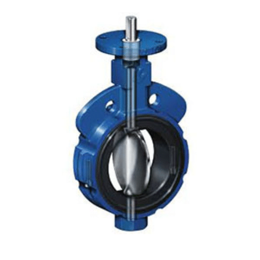
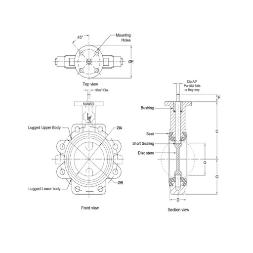
BUTTERFLY VALVE EPDM & EPDM + PTFE seated Centric design
Applications :
Food and beverages, slurries, pneumatic conveying, dry bulk conveying, chemicals, paper stock, mineral processing. This type of valve is highly suitable where bubble-tight shut off with maximum flow area is required.
Suitable for on-off and control services
TECHNICAL DATA
Size: 2” (50 mm) to 20” (500 mm)
Type: Wafer & Lug Design: Centric Bi-directional Pressure: PN10, PN16 Seat: EPDM, PTFE + EPDM Flange Suit To: ANSI 150#, PN10, PN16, BS TableDesign, Manufacturing and Testing Standards – Technology at a Glance
Kansei EPDM and PTFE Centric Bi-directional Butterfly valves are designed to ensure a bubble tight shut off in both direction and provide a Maximum flow area. “A major advantage of Kansei product is an International compatibility.”
The Exclusive Design of two-piece body with one-piece wafer-thin disc stem provide the very less obstruction to flow. Body locating holes provide easy placing and perfect centering of the valve between the flanges. Rounded & Buffed disc edge gives full concentric sealing with lower torque, which gives longer seat life. Kansei designed Primary stem sealing accomplished by a preinstalled contact between seat surface and rounded disc hub area which overtake the pressure rating of valve and prevents the leakage through the stem area to atmosphere. An inbuild ‘O’ ring on the seat surface provide flange sealing and eliminates the need for additional flange gasket. The seat is completely field replaceable and isolated from line media which allows superior performance of valve with extended service life. The seat design in such a way to ensure seal drop-tight and bi-directional at low to high pressure range. Split body for easy maintenance. This product is not recommended for dead end services. This type of valve can be installed in vertical or horizontal pipeline and any intermediate orientation.- Design standard as per EN 593/BS 5155 as standard, another applicable standard on request.
- Testing standard as per API 598 or EN 12266-1 as standard.
- Certificate EN10204 Type 3.1 as standard & Manufacturing under Quality system ISO 9001: 2015.
- Casting inspection as per MSS-SP-55 as standard. Another applicable standard on request.
- Trims available with combination of various Casting material like CI/ DI/ WCB/ CF8/ CF8M/ CF3M/ GR. 4A-5A/ etc. and Seat Material like EPDM / EPDM+PTFE etc.
- 100% factory tested (Hydro, Pneumatic) and Inspected valves as per standard.

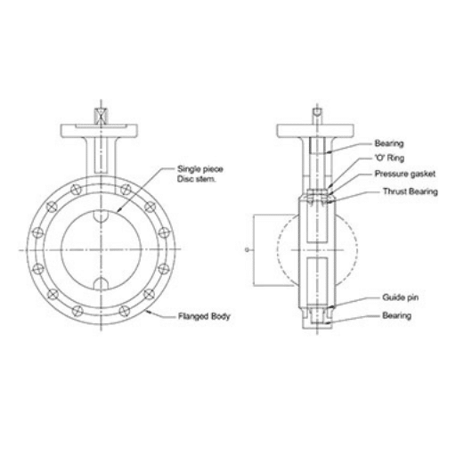
BUTTERFLY VALVE PFA/PTFE Lined, Centric Bi-directional
Applications :
This type of valves are used for multitude and corrosive application, Hazardous and pure liquid, gas, & vapors, free flowing. e.g.: Pharma, foundries and mining, chemicals and petrochemicals, pulp and paper industries, under vessels, & specially used where constant torque and no maintenance is required . Suitable for on-off and control servicesTECHNICAL DATA
Type: Wafer type, Lug type, Flange typeWafer type & Lug type Size: 2” (50 mm) to 12” (300 mm)
Flange type Size: 14” (350 mm) to 16” (400 mm) Design: Centric Bi-directional Pressure: PN10, PN16 Seat: PTFE, PFA, PFA CONDUCTIVE, TFM, TFM CONDUCTIVE Flange Suit To: ANSI 150#Design, Manufacturing and Testing Standards – Technology at a Glance
Kansei PFA/PTFE Lined Centric Bi-directional Butterfly valves are designed to ensure a tight fit around the disc for bubble tight shut off in both direction and provide a constant torque with no maintenance. “A major advantage of Kansei product is an International compatibility.”
The Exceptional Design of one-piece thin disc stem lined with 3mm molded PFA providing high Kv value. The liner and disc are the only two valve parts in contact with the medium. Kansei improved design of disc leading to less deflection at higher pressure and tighter in line seal and for stem sealing system. Primary shaft sealing by preloaded contact between disc and liner hub and the secondary shaft seal by oversizing the shaft diameter in relation to the shaft hole in the liner. The liner and disc are molded and machined to close tolerances to provide low torque, less stress and deformation using opening and closing. PTFE atmospheric seat protects internal components from atmospheric corrosion and provides locating ring for actuator mounting. Fully encapsulated bottom shaft eliminates potential leak path at bottom of valve and eliminates the necessity for further sealing elements- Design standard as per EN 593 or API 609 as standard, another applicable standard on request.
- Testing standard as per API 598 or BS EN 12266-I as standard. 100% bubble tight shut off valve.
- Certificate EN10204 Type 3.1 as standard & Manufacturing under Quality system ISO 9001: 2015.
- Casting inspection as per MSS-SP-55 as standard. Another applicable standard on request.
- Trims available with combination of various Casting material like CI/ DI/ WCB/ CF8M/ CF3M/ GR. 4A-5A/ etc. and Seat Material PTFE.
- 100% factory tested (Hydro, Pneumatic) and Inspected valves as per standard.
- Lever / Gear / Pneumatic / Electric Operation as per customer requirement.
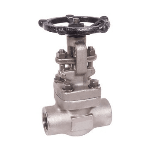
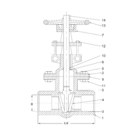
GATE VALVE, Screw End (150#, 300#)
| Design Std. | As per BS 5352/ ASME B16.34 |
| End Connection | Screw End |
| Testing & Std. | As per API 598 / ISO 5208 |
| Size, 150# | 15 mm to 50 mm (1/2" to 2") |
Bill Of Material
| Sr. No. | Description | Material |
| 1 | Body | WCB / CF8 / CF8M |
| 2 | Bonnet | WCB / CF8 / CF8M |
| 3 | Wedge | WCB (13% CR) / CF8 / CF8M |
| 4 | Seat Ring | SS410 (13% CR) / CF8 / CF8M |
| 5 | Stem | SS410 / SS304 / SS316 |
| 6 | Gland | SS410 / SS304 / SS316 |
| 7 | Yoke Sleeve | SS410 / SS304 / SS316 |
| 8 | Back Seat Bush | CS/CF8/CF8M |
| 9 | Gasket | EN8 |
| 10 | Gland Packing | MS/SS |
| 11 | Bonet Stud | MALLEABLE IRON |
| 12 | Bolt | MS |
| 13 | Hand wheel | SPW SS304 GRAPHITE FILLED |
| 14 | Hand wheel Nut | GRAPHITE |
Dimensions 150#
Technical Data
| Size | F/F | B |
| 15 | 85 | 21.7 |
| 20 | 92 | 27.1 |
| 25 | 106 | 33.8 |
| 30 | 122 | 42.6 |
| 40 | 127 | 48.5 |
| 50 | 140 | 50.8 |
All dimensions are in mm.


Sandwich Type Non Return Valve ( NRV )(PN10 , PN16)
TECHNICAL DATA
| Design Std. | As per API 6D |
| Testing Std. | As per EN-12266-1 |
| End Connection | ANSI B16.5(150#), B16.47(300#) |
| Size | 30 mm to 300 mm, PN10 / PN16 |
Dimensions PN10
| Size | Dia A | Dia B | L |
| 30 | 16 | 84 | 16 |
| 40 | 22 | 94 | 16 |
| 50 | 30 | 109 | 16 |
| 65 | 37 | 129 | 16 |
| 80 | 48 | 144 | 16 |
| 100 | 70 | 164 | 16 |
| 125 | 95 | 194 | 18 |
| 150 | 121 | 220 | 19 |
| 200 | 155 | 275 | 29 |
| 250 | 196 | 330 | 29 |
| 300 | 230 | 380 | 38 |
Dimensions PN16
| Size | Dia A | Dia B | L |
| 30 | 16 | 84 | 16 |
| 40 | 22 | 94 | 16 |
| 50 | 30 | 109 | 16 |
| 65 | 37 | 129 | 16 |
| 80 | 48 | 144 | 16 |
| 100 | 70 | 164 | 16 |
| 125 | 95 | 194 | 18 |
| 150 | 121 | 220 | 19 |
| 200 | 155 | 275 | 29 |
| 250 | 196 | 331 | 29 |
| 300 | 230 | 386 | 38 |
All dimensions are in mm.
