

")
")
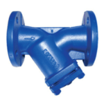
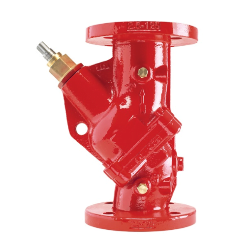
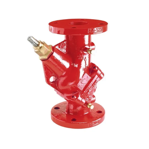
Y-Type Strainers (ANSI 150#, 300#)
Applications:
Strainer can be used in liquid as well as gas line, Regulator and valve protection, steam traps protections, flow meter and pump protections, heat exchanger and refrigeration set protection, Suitable for Hazardous environments.
Y-Strainers and pot basket type strainers is a device for mechanically removing unwanted solids from liquid, gas or steam lines by means of a perforated or wire mesh straining element. Where the amount of material to be removed from the flow is relatively small, resulting in long intervals between screen cleanings, the strainer screen is manually cleaned by shutting down the line and removing the strainer cap
Technical Data :
| Design Std. | As per ASME B16.34 |
| Testing Std. | As per API 598 |
| End Connection | Flanged End as per ANSI B16.5, F to F as per ANSI B16.10 |
| Shell Wall Thickness | As per ANSI B16.34 |
| Size 150# & 300# | 50 mm to 300 mm (2” to 12”) |
| Standard Trims | WCB / CF8M, Mesh : SS |
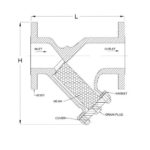
Dimensions 150#
| Size | ~L | ~H |
| 50 | 225 | 190 |
| 80 | 315 | 270 |
| 100 | 370 | 305 |
| 150 | 470 | 400 |
| 200 | 600 | 490 |
| 250 | 695 | 670 |
| 300 | 810 | 800 |
Dimensions 300#
| Size | ~L | ~H |
| 50 | 270 | 190 |
| 80 | 320 | 270 |
| 100 | 355 | 305 |
| 150 | 450 | 400 |
| 200 | 560 | 490 |
| 250 | 730 | 670 |
| 300 | 850 | 800 |
All dimensions are in mm.
General Notes :
- Customization and Automation as per customer requirements.
- Certificate of compliance to EN10204 Type 3.1 as standard.
- Safety stock as per customer requirements.
- 100% factory tested and inspected valves as per standard.
- Other trims also available as per customer requirements.
- Support to customers for other product requirements from sources.
- Consult to Factory for Other Details.
Related products
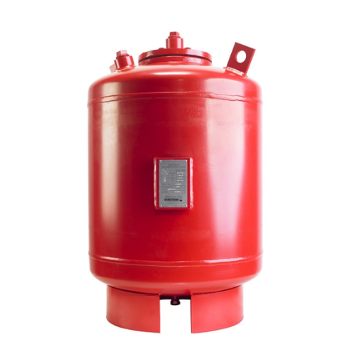
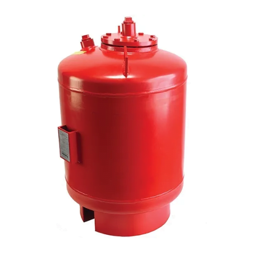
Armstrong Expansion Tanks
- Applications-Pressure stabilization in water based mechanical systems such as booster installations, boiler systems, and chiller plants
- Description-Armstrong Expansion Tanks are designed to reduce tank sizes by up to 80% over standard designs. Expansion tanks use compressed air to maintain system pressures by accepting and expelling the changing volume of water as it heats and cools. Diaphragm or bladder tank designs isolate the expanded water from the pressure controlling air cushion – which is pre-charged at the factory and can be adjusted in the field to meet final system requirements
- Materials (MOC)-Carbon steel (shell), heavy duty Butyl (diaphragm)
- Performance range-AET plain steel expansion tanks: 15 to 525 USgpm flow. AX diaphragm expansion tanks: 8 to 211 USgpm flow. Type L bladder type expansion tanks: 10 to 1056 USgpm flow.
Armstrong Flo-Trex Valves
- Applications-HVAC-system pumping; general purpose pumping; industrial/ process pumping (water or glycol based).
- Description-The Armstrong Flo-Trex Valves (FTV) are multi-function pump fittings that reduce equipment and installation costs.
- Materials (MOC)-Cast iron, ductile iron; grooved, flanged or threaded connections.
- Performance range-Suitable for all Armstrong commercial pumps.
- Temperature-230 °F (110 °C)
- Size-1.25” to 20” (32 mm to 500 mm)
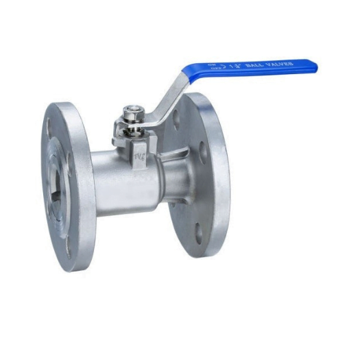
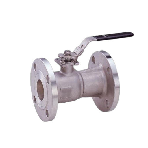
Ball Valves One/Two Piece, Fire Safe-Antistatic design, Full bore Flange end (150#,300#)
Description
One Piece body from DN 15 to DN 40 and Two-piece design from DN 50 to DN 200 valve size. Ideally suitable for use in oil and gas production, refining and chemical applications. Body material and wetted trim components confirms to NACE standard MR 0175. Fire safe and Anti-static design where Hazardous areas with handling of flammable fuels, gases or chemicals are in use.Technical Data :
- Size Range: DN 15 – DN 40 (One piece), DN 50 – DN 200 (Two piece)
- Pressure rating: ASME Class 150 & 300
- Temperature range: Up to 260 deg. C
- Seat: PTFE / Carbon Reinforced PTFE
- End Connections: Flanged ASME B16.5
- With & Without ISO PAD
- MOC : WCB, PTFE, CF8, 304 S/S, 316 S/S, MS, CF8M, SS, Carbon R’PTFE
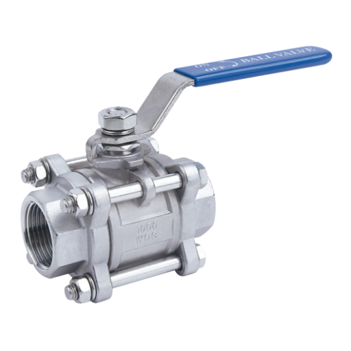
Ball Valves Three Piece, Full Bore (Screw End, Socket Weld) (150#, 300#, 600#, 800#)
Technical Data :
| Design Std. | As per ISO 17292 & BS 5351 |
| End Connection | Screwed End/Socket Weld |
| Testing & Std. | As per API 598 / ISO 5208 |
| Size, 150# | 15 mm to 50 mm (1/2" to 2") |
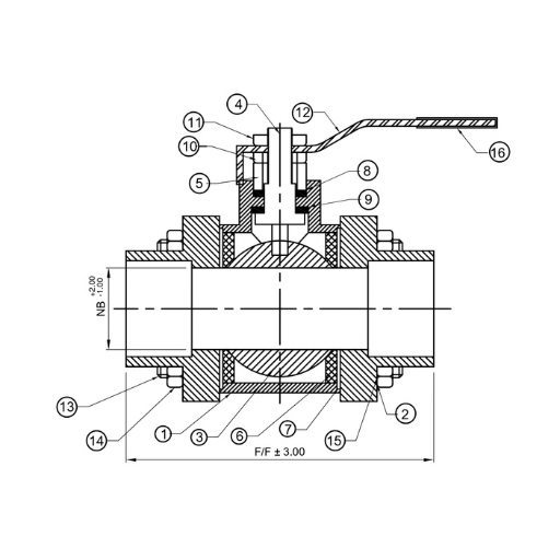
Material (MOC)
| Sr. No. | Description | Material |
| 1 | Body | WCB / CF8 / CF8M |
| 2 | Adaptor | WCB / CF8 / CF8M |
| 3 | Ball | CF8 / CF8M |
| 4 | Steam | SS304 / SS316 |
| 5 | Gland | SS304 / SS316 |
| 6 | Seat Ring | PTFE / GFT /CFT |
| 7 | Body Seal | PTFE / GFT /CFT |
| 8 | Gland Packing | PTFE / GFT /CFT |
| 9 | Steam Seal | PTFE / GFT /CFT |
| 10 | Gland Nut | MS/SS304 |
| 11 | Lever Nut | MS/SS304 |
| 12 | Lever | MS/SS |
| 13 | Stud | MS/SS304 |
| 14 | Stud Nut | MS/SS304 |
| 15 | Stud Washer | MS/SS304 |
| 16 | Lever Sleeve | PVC |
Dimensions 150#
| Size | NB | F/F | Thread Type |
| 15 | 12.5 | 62.5 | BSP/NPT/SW |
| 20 | 19.0 | 74.0 | BSP/NPT/SW |
| 25 | 25.0 | 87.0 | BSP/NPT/SW |
| 40 | 38.0 | 109.0 | BSP/NPT/SW |
| 50 | 50.0 | 110.0 | BSP/NPT/SW |
All Dimensions are in mm
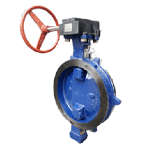
BUTTERFLY VALVE High Performance Double Offset
Applications :
Pharma, Military, Sour gas, Food Processing, Vacuum and Oxygen services, Steam services, Dead-end services, Fire, Chemical industry e.g. Chlorine-Ammonia etc., Reverse Osmosis, Slurry services, Modulating or Special fluids where Flow control is Important.TECHNICAL DATA
Size: 2” (50 mm) to 36” (900 mm)
Type: Wafer, Lug, Flange Design: Eccentric-Double offset Pressure: ANSI Class 150-300 Seat: RTFE, PTFE, UHMWPE, Metal, Fire Safe Flange Suit To: ANSI 150#,300#Design, Manufacturing and Testing Standards – Technology at a Glance
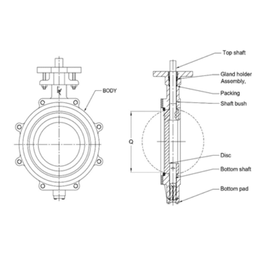
Kansei Wafer, Lug and Flanged Double offset butterfly valves are designed to ensure minimum seat wear, zero leakage shutoff throughout the full pressure range and Uni-Bidirectional to provide a long service life with minimum maintenance. “A major advantage of Kansei product is an International compatibility.”
The Superior two-piece stem design and double offset disc/stem design allows high cycling and eliminates seat deformation when the disc is in the open position. At the initial point of disc opening, the offset disc produces a cam action and pulling the disc from the seat. During opening, disc does not contact the seat which ensures the maximum seat service life with reduced operating torques. The first offset is by locating the stems downstream of the center line of the seat which allows 360-degree unobstructed sealing surface. The second offset is by locating the stems off-center of the vertical axis of the seat. As the valve closes, the camming action converts the rotary motion of the disc to a linear motion which effectively push the disc on seat. Mounting pads integrally casted which provides direct mounting of Gear box and Actuators on valves. Torque requirements of the Kansei High performance double offset valve is significantly lower. The seat is completely isolated from all contact with the line media which allows superior performance of valve with extended service life. Serrations of the seat retainer ring and body secure the seat assembly in place irrespective of disc position. Line media seals to Zero-leakage in both directions and seat is self-adjusting to absorb wear and temperature changes. Replacement of seat is also easy without disturbing the disc or stem. The seat design in such a way to ensure seal drop-tight and bi-directional at low to high pressure range. Seat incorporates a Stainless-Steel wire winding with U-shape envelope to provide better seat life. The wire allows flexibility in both direction of flow. Fire safe: Kansei High performance double offset valves having firesafe seat design options in wafer, lug and flange valves. Fire safe design combines superior performance, extended service life. In normal service, the fire safe design with Soft seat and Metal seat to ensure zero-leakage in both directions of line media flow in full rated pressure and temperature range. In the fire condition, soft seat will be destroyed either partially or fully by excessive heat and metal seat will take place to provide constant sealing. Fire safe packing arrangement with three rings of graphite to create a superior and high temperature sealing.- Design standard as per EN 593 or API 609 (cat. B) as standard, another applicable standard on request.
- Testing standard as per API 598 and FCI 70-2.
- Certificate EN10204 Type 3.1 as standard & Manufacturing under Quality system ISO 9001: 2015.
- Casting inspection as per MSS-SP-55 as standard. Another applicable standard on request.
- Trims available with combination of various Casting material like WCB/ CF8/ CF8M/ CF3M/ GR. 4A-5A/ NAB/ Aluminum Alloys etc. and Seat Material like RTEF/ PTFE/ UHMWPE/ METAL/ FIRE SAFE.
- 100% factory tested (Hydro, Pneumatic) and Inspected valves as per standard.
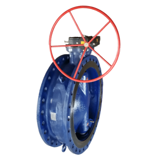
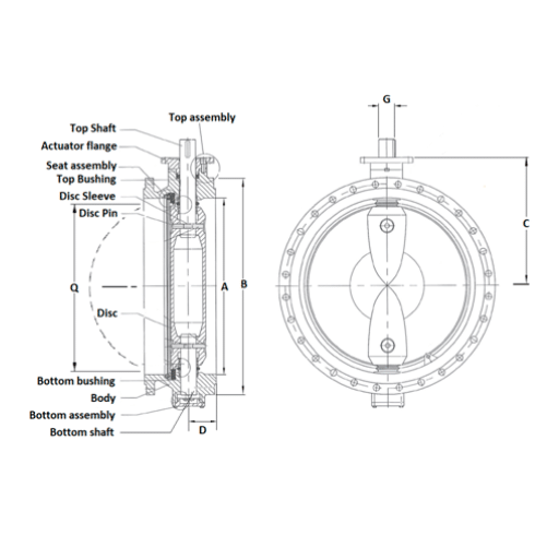
BUTTERFLY VALVE Large Size Double Flanged, Eccentric Design
Applications:
Power plants, Water works, Municipal water treatment, Cooling systems, Industrial applications etc.TECHNICAL DATA
Suitable for on-off and control services Size: 20” (500 mm) to 80” (2000 mm) Type: Double Flanged Design: Eccentric Pressure: PN6, PN10, PN16, PN20, PN25 Seat: EPDM, BUNA-N, VITON Flange Suit To: PN6, PN10, PN16, PN20, PN25,ANSI, JIS ANSI, BS, DIN, ISO, ISDesign, Manufacturing and Testing Standards – Technology at a Glance
Kansei Double flanged Eccentric Large Butterfly valves are designed to accommodate Flange drilling JIS, ANSI, DIN, BS. Also providing dead-end service capability with downstream piping removed. Each size valve flange has been designed to have the maximum outside diameter and maximum thickness of the nominated flange standards. K35 type valves provides the robust features to ensure reliable performance and long service life. “A major advantage of Kansei product is an International compatibility.”
The valve face to face in accordance with EN 558, BS 5155 Short, ISO 5752 Table 4, EN-593 and AWWA C-504, AWWA C-207. Mounting cast flange designed in accordance to ISO 5211. The Replaceable Seat design meets the requirements of seat replaceability on field without special tooling, dismantling and removing the valve from line. Also provide better shut-off and longer service life. The seat is of a molded construction and fits easily into the body which also reduce seating torque with disc edge contours. The Seat is adjustable to optimize the required shut-off tightness to comply the torque both for unidirectional and directional operation. The Eccentric design provides energy efficient flow control. Stainless steel disc edge protects against corrosion and eliminates the possibility of restricted sealing. Upper and Lower shaft bearings prevent shaft deflection and provide optimum guidance to increase the valve life. High strength and Full diameter Shafts remain dry and provides positive disc control with a minimum flow restriction. Sleeve bearings are self-lubricated which allows valve installation with the shaft vertical or horizontal. Thrust bearings are provided with the adjustment to ensure good axial positioning of the disc due to forces applied by seat and shaft seals to the disc. The secondary seal is provided to seal the bearing area from environment, and it will also act as a primary seal in account of failure of primary seal, Rubber lining is additional option for this product.- Design standard as per EN 593, AWWA C-504, AWWA C-207 as standard, another applicable standard on request.
- Testing standard as per API 598 or BS EN 12266-I as standard. 100% bubble tight shut off valve.
- Certificate EN10204 Type 3.1 as standard & Manufacturing under Quality system ISO 9001: 2015.
- Casting inspection as per MSS-SP-55 as standard. Another applicable standard on request.
- Trims available with combination of various Casting material like CI / DI / NICI / NIDI / WCB / CF8 / CF8M / CF3M/ GR. 4A-5A / NAB etc. and Seat Material like EPDM / BUNA-N / VITON etc. Coating and Lining as per Customer requirement.
- 100% factory tested (Hydro, Pneumatic) and Inspected valves as per standard.
- Gear / Pneumatic / Electric / Hydraulic Operation as per customer requirement.


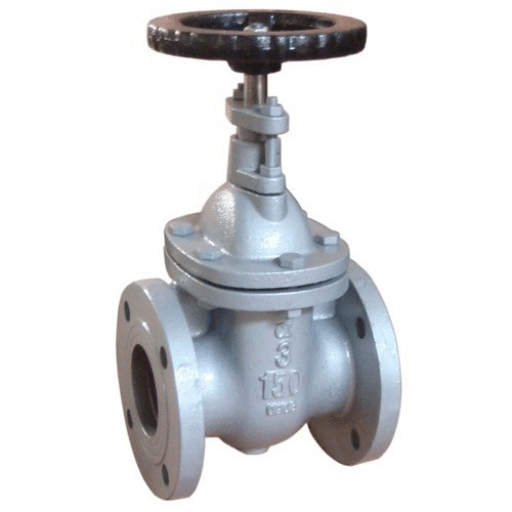
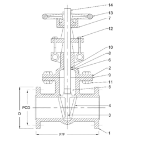
GATE VALVE, Flanged End (150# , 300#)
Technical Data
| Design Std. | As per BS 1414 |
| End Connection | Flanged End |
| Testing & Std. | As per API 598 / ISO 5208 |
| Size, 150# & 300# | 15 mm to 300 mm (1/2" to 12") |
Bill Of Material
| Sr. No. | Description | Material |
| 1 | Body | WCB / CF8 / CF8M |
| 2 | Bonnet | WCB / CF8 / CF8M |
| 3 | Wedge | WCB (13% CR) / CF8 / CF8M |
| 4 | Seat Ring | SS410 (13% CR) / CF8 / CF8M |
| 5 | Stem | SS410 / SS304 / SS316 |
| 6 | Gland | SS410 / SS304 / SS316 |
| 7 | Yoke Sleeve | SS410 / SS304 / SS316 |
| 8 | Back Seat Bush | CS/CF8/CF8M |
| 9 | Gasket | EN8 |
| 10 | Gland Packing | MS/SS |
| 11 | Bonet Stud | MALLEABLE IRON |
| 12 | Bolt | MS |
| 13 | Hand wheel | SPW SS304 GRAPHITE FILLED |
| 14 | Hand wheel Nut | GRAPHITE |
Dimensions 150#
| Size | Dia D | PCD | F/F |
| 15 | 90 | 60.5 | 108 |
| 20 | 100 | 70 | 117 |
| 25 | 110 | 79.5 | 127 |
| 40 | 125 | 98.5 | 165 |
| 50 | 150 | 120.5 | 178 |
| 65 | 180 | 139.5 | 191 |
| 80 | 190 | 152.5 | 203 |
| 100 | 230 | 190.5 | 229 |
| 150 | 280 | 241.5 | 267 |
| 200 | 345 | 298.5 | 292 |
| 250 | 405 | 362 | 330 |
| 300 | 485 | 432 | 356 |
Dimensions 300#
| Size | Dia D | PCD | F/F |
| 15 | 95 | 66.5 | 140 |
| 20 | 115 | 82.5 | 152 |
| 25 | 125 | 89 | 165 |
| 40 | 155 | 114.5 | 190 |
| 50 | 165 | 127 | 216 |
| 65 | 190 | 149 | 241 |
| 80 | 210 | 168.5 | 283 |
| 100 | 255 | 200 | 305 |
| 150 | 320 | 270 | 403 |
| 200 | 380 | 330 | 419 |
| 250 | 445 | 387.5 | 457 |
| 300 | 520 | 451 | 502 |
All dimensions are in mm.
